
This article was first published on Medium.
The automotive sector is fast evolving with the expectation from both manufacturers and investors to stay agile. Traditional tools, often as paid utilities, are slowly becoming things of the past, and there is a shift toward using more open-source libraries to enhance existing processes. In this article, I will discuss how Pybind11 was used to combine a C++ library for parsing BLF (binary logging format) files with existing Python code to achieve more accuracy and speed. Rather than talking about how to use Pybind11, which many other sources have already accomplished, I want to dive deep into the engineering of why I chose to use it.
It was not a first choice or even the second, considering it adds one more node of complexity to the process, as you will read later. However, I care about accuracy more than speed or code brevity, and the additional C++ library with Pybind11 provided just that. I break this article down into two main sections: the first section discusses BLF files and their details, and the second section touches on the code.
Binary Logging Format (BLF) #
Brief background of automotive testing #
In the automotive industry, communication between various components (engines, motors, sensors, etc.) and electronic control units (microcontrollers with control logic) primarily happens over controller area (CAN) and local interconnect (LIN) networks. Communication over these networks is broken down into messages, and each message contains various signals. This communication helps the automobile work according to consumer expectations, where the electronic control units command various components to take certain actions depending on various inputs.
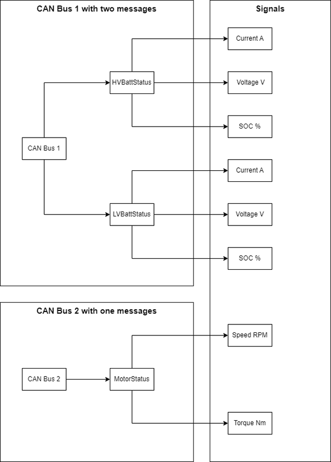
CAN is a hierarchical system with a bus → message → signal structure, as shown in the figure below. Communication on the CAN (Controller Area Network) system is organized into multiple buses. This organization can vary based on the specific system; for instance, battery and powertrain messages are transmitted on separate CAN buses. Each bus contains multiple messages, and each message comprises several signals. Each message includes signal measurement data, but the timestamp for the measurement is associated with the message itself. This setup ensures that all signals are communicated with the same timestamp.
Automotive manufacturers thoroughly test their products, from individual components, disparate and interconnected systems, and the entire vehicle, expanding the testing boundary wider with each step. As a result, large amounts of such communication data are generated from data loggers in two popular formats: the binary logging format (BLF) and the measurement data format version 4 (MF4).
File details #
BLF format was created by Vector Informatik GMBH who also provide the necessary data acquisition hardware (loggers) and software (CANalyzer, CANape, etc.) popular in companies to record data. As the name suggests, the data is stored in binary format, which enables the storage of large amounts of data with comparatively low file sizes. The benefits of this are seen during long test drives (city A to city B through some extreme terrain and weather) where data is logged continuously.
The BLF file is divided into multiple sections, which are enumerated below. Of course, not all files have all the sections because it depends on the data being recorded, the configuration of the logger, the number of CAN/LIN buses involved, etc.
- A file header
LOGG - Log objects with containers that store the data
LOBJ - System and environment variables
- Internal events
- Markers
- Comments
The file header and log objects are the most prevalent in most BLF files. The abridged output of a hexdump for a typical BLF file is shown below:
00000000  4f f0 34 34 20 00 00 00  36 68 4f 00 04 01 0f 05  |LOGG....h6M.....|
00000010  b4 ae 34 00 00 00 00 00  ec 15 e9 00 00 00 00 00  |..4.............|
00000020  5b 12 04 00 17 00 00 00  f0 07 0a 00 05 00 04 00  |................|
00000030  34 00 03 00 48 00 20 02  f0 07 0a 00 05 00 04 00  |....2. .........|
00000040  34 00 04 00 1c 00 99 02  e8 a1 34 00 00 00 00 00  |..........4.....|
00000050  4c 0c 00 00 32 00 00 00  00 00 00 00 00 00 00 00  |l...H...........|
00000060  01 00 00 00 00 00 00 00  00 00 00 00 00 00 00 00  |................|
*
00000090  6c 4f 42 5a 10 00 01 00  c9 68 00 00 0a 00 00 00  |LOBJ.....b......|
000000a0  05 00 00 01 00 00 00 00  00 00 02 00 f9 7f 00 00  |................|
000000b0  90 01 ad 5f 05 5c 15 cb  f7 5f b8 17 bc 76 77 21  |x..].\..._...vw!|
File Parsing #
BLF file parsing is a two-step process.
Step 1 #
In the first step, binary logs are parsed to retrieve information related to object IDs for all timestamps. This produces an output, as shown below, with a running list of object IDs with signal measurement as bytes. With this information alone, it is very hard to discern what each object ID represents and the signal value from the byte data. For example, is the first ID (08c) HVBattStatus or LVBattStatus or something else, and which byte represents which signal? There is no indication about the units of any given signal either. This is exacerbated if there are multiple CAN and LIN buses with hundreds of messages.
To illustrate the large amounts of communication for a real-world product, consider a vehicle I worked on recently. One electronic control unit (out of eleven) used six CAN buses and one LIN bus. That amounted to one thousand ninety-nine (1099) CAN messages and twelve (12) LIN messages. Therefore, to overcome the complexity, CAN and LIN database files are created that are specific to the application. Each CAN bus gets one database file with all the information about its messages, signals, enumerations, etc. These are discussed in Step 2.
Timestamp:1728097465.163524 ID:08c DL:7  00 00 00 00 00 96 00        Channel: 3
Timestamp:1728097465.163750 ID:08d DL:7  00 00 00 00 00 96 00        Channel: 3
Timestamp:1728097465.163978 ID:08e DL:7  00 00 00 00 00 96 00        Channel: 3
Timestamp:1728097465.164228 ID:76f DL:8  00 00 00 00 00 00 00 00     Channel: 3
Timestamp:1728097465.151284 ID:600 DL:8  5a 00 00 00 00 00 00 00     Channel: 0
Timestamp:1728097465.151365 ID:220 DL:8  2a 36 ff 7f 00 00 e0 7f     Channel: 1
Timestamp:1728097465.151454 ID:010 DL:4  7a 12 0c 00                 Channel: 0
Timestamp:1728097465.151603 ID:224 DL:8  26 36 f8 3d fc cf 07 00     Channel: 1
Timestamp:1728097465.151700 ID:601 DL:8  5a 00 00 00 00 00 00 00     Channel: 0
Timestamp:1728097465.151781 ID:520 DL:5  eb 06 6e dc 77              Channel: 1
Timestamp:1728097465.151870 ID:011 DL:4  7a 12 0c 00                 Channel: 0
Timestamp:1728097465.152019 ID:222 DL:8  d9 36 ff 7f 00 00 e0 7f     Channel: 1
Timestamp:1728097465.152116 ID:602 DL:8  5a 00 00 00 00 00 00 00     Channel: 0
Timestamp:1728097465.152251 ID:226 DL:8  49 36 f8 3d fc cf 07 00     Channel: 1
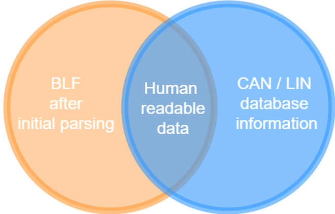
Step 2 #
In this step, the output from Step 1 and the contents of the database files are compared to obtain human-readable data. Database files are in the format shown below. It contains all the information to parse a message’s data with its signal values. 01 is the object ID of the message HVBattStatus that is 3 bytes in length sent by HVBatt. It has three signals: current, voltage, and SOC, each representing 1 data byte. The Current signal data is in the first byte of the three bytes of the message, from the 0th bit to the 8th bit, i.e., 0|8 as a Little Endian byte order (@1). The signal has a multiplier of 1 and scaling of 0 (1, 0); if the value obtained from the byte is 50, the current signal measurement is $current = 50 \times 1 + 0$. Current has a minimum and maximum value of -100 and 100, respectively: [-100|100], with the unit A for ampere. Notice the change in maximum/minimum values for the LV battery’s current and voltage.
# For CAN Bus 1

BO_ 01 HVBattStatus : 3 HVBatt
 SG_ Current  : 0|8@1- (1,0) [-100|100] "A" ECU1
 SG_ Voltage  : 8|8@1+ (1,0) [0|500] "V" ECU1
 SG_ SOC  : 16|8@1+ (1,0) [0|100] "%" ECU1

BO_ 02 LVBattStatus : 3 LVBatt
 SG_ Current  : 0|8@1- (1,0) [-10|10] "A" ECU1
 SG_ Voltage  : 8|8@1+ (1,0) [0|24] "V" ECU1
 SG_ SOC  : 16|8@1+ (1,0) [0|100] "%" ECU1
Culmination of tools #
What are we solving #
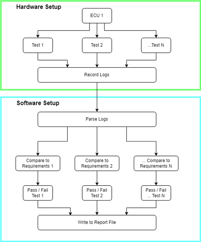
As I touched on briefly, auto manufacturers thoroughly test individual components, systems, and full vehicles to ensure safety, reliability, and optimum quality. As part of testing individual components, a methodology called hardware-in-the-loop (HIL) is employed to test control logic, where an electronic control unit is isolated for testing control logic. In this setup, multiple tests are run sequentially to validate sections of the control logic, akin to integration tests done for a software-as-a-service application. Each test produces a log file, i.e., BLF file, and must be parsed and analyzed to provide a pass/fail result.
The process diagram below highlights two main setups: hardware and software. The former is a legacy tool that cannot be easily replaced without financial support. The latter is the most important, in my opinion, because it takes the logs from the test data, analyzes them, and outputs a result. Inaccuracy here could lead to false positives or negatives, which could have dire consequences later. The software section, in the previous iteration, was written wholly in Python. The “Parse Logs” process took care of both the steps of parsing the BLF file in one environment.
Python was chosen because of its versatility and large community. One such library, cantools, can consume CAN database files and raw data from the BLF (after parsing step 1) to output readable human data. Venerable libraries like numpy and pandas enable post-processing on this data, which is vital for comparing the results with the requirements. Finally, openpyxl helps write results for a report file. Furthermore, most simulation/data analysis engineers in automotive are familiar with MATLAB programming, and Python serves as a valid replacement, softening the learning curve.
However, there were some problems with accuracy while parsing log files, especially with respect to multiplexed CAN messages. Multiplexed CAN messages are unique, and an article would be needed to explain them in detail. Very briefly: multiplexed messages are able to read different signals from the same byte data depending on the first-byte value. This was an edge case situation, and we used to manually analyze those logs to provide a result; there was no harm in analyzing a couple of files manually. However, what once was an edge case became a normal occurrence, and a process change was needed for us to stay agile.
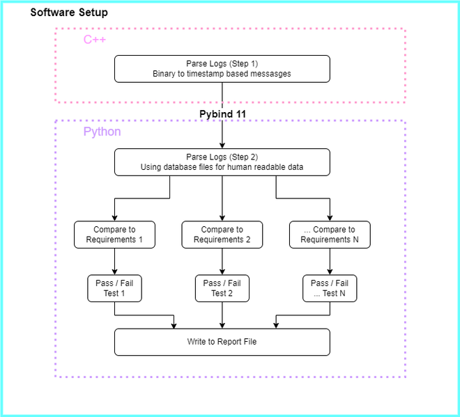
After careful review of the problem, I noticed that the problem was in the first step of the parsing, i.e. getting message data per timestamp from the binary file. Therefore, the “Parse Logs” step was divided into two steps, each having its own environment. This is where the language choice becomes apparent.
C++ library #
Accuracy was the main focus for splitting the process into two steps and venturing out to find new tooling. I tried multiple Python libraries to maintain the same environment, but neither one had the functionality and versatility that I was expecting. I even tried convincing the team to change the file format from BLF to MF4, which is more open-source, and documentation of the file structure is easily available. This enables new tooling to be created or found for its parsing within the community. However, that hit a stone wall quickly because asking the entire group to change the file format is hard.
I found a C++ library vector_blf that was accurate with step 1 of the BLF file parsing. Multiple files were tested to ensure that the output matched what the paid software outputted for the same files. Moreover, this library provides a vast array of functionality to extract not only objects from the BLF file but also comments, markers, and variables. The rest of the article will focus only on getting CAN objects from the files. Building the library was straightforward, credit to its easy-to-read README:
mkdir build; cd build
cmake ..
make
make install DESTDIR='/home/user/Projects/vector_blf/installed'
This produces a shared object for the vector_blf library that can be used with its respective headers. The library can be linked with other C++ code. This is also one of the reasons for choosing C++ here: it allowed linking libraries to existing C++ tooling that other teams within the company used.
├── include
│   └── Vector
├── lib
│   ├── libVector_BLF.so -> libVector_BLF.so.2
│   ├── libVector_BLF.so.2 -> libVector_BLF.so.2.4.2
│   ├── libVector_BLF.so.2.4.2
│   └── pkgconfig
Using Pybind11 to consolidate #
The decision to use Pybind11 was made through a simple Google search, “use C++ code in Python.” Another option that emulates the same functionality is in the venerable Boost library. However, I found its documentation to be confusing and needing a lot more downloads.
The complete repository tree structure, including the Python files, is shown below. The cpp_artifacts folder includes all the folders related to C++ code. pybind11 is added as a submodule to the repository as mentioned in their documentation. vector_blf has the same contents as shown in the previous section.
├── README.md
├── xmb
│   ├── __init__.py
│   ├── cpp_artifacts
│   │   ├── CMakeLists.txt
│   │   ├── parse_can_msg.cpp
│   │   ├── pybind11
│   │   └── vector_blf
│   ├── parse_blf.cpython-39-x86_64-linux-gnu.so
│   ├── parse_blf.pyi
│   ├── read_blf_data.py
│   └── utils.py
├── pyproject.toml
└── requirements.txt
To use Pybind11, the parse_can_msg.cpp file was created to expose C++ functions and enumerations to Python. It is recommended as per the documentation of Pybind11, to separate implementation code from ‘exposure’ code. I did not follow this in the first iteration, due to its proof-of-concept nature.
#include <pybind11/pybind11.h>
#include <pybind11/stl.h>
#include <pybind11/complex.h>
#include <pybind11/functional.h>
#include <pybind11/chrono.h>
#include <pybind11/stl_bind.h>
#include <Vector/BLF.h>

std::vector<Vector::BLF::CanMessage2 *> parse_blf(std::string blf_filename) {
 Vector::BLF::File file;
    std::cout << blf_filename << std::endl;
    file.open(blf_filename.c_str());
 ...
}

PYBIND11_MAKE_OPAQUE(std::vector<uint8_t>);
PYBIND11_MODULE(parse_blf, m) {
    m.doc() = "BLF parser written in C++ by Technica-Engineering";
    m.def("parse_blf", &parse_blf, "Parses BLF files and returns a vector of CanMessage2 objects",
    py::arg("blf_filename"));
    py::class_<Vector::BLF::CanMessage2>(m, "Vector_BLF_CanMessage2")
        .def(py::init<>())
        .def_readwrite("channel", &Vector::BLF::CanMessage2::channel)
        // ... repeat for other properties;

    py::enum_<Vector::BLF::ObjectHeader::ObjectFlags>(m, "Vector_BLF_ObjectHeader_ObjFlags")
        .value("TimeTenMics", Vector::BLF::ObjectHeader::ObjectFlags::TimeTenMics)
        .value("TimeOneNans", Vector::BLF::ObjectHeader::ObjectFlags::TimeOneNans)
        .export_values();

 // ... other classes and enumerations
    py::bind_vector<std::vector<uint8_t>>(m, "VectorUint8");
}
parse_blf library for Python consumption was built using g++. This creates a shared object file, parse_blf.cpython-39-x86_64-linux-gnu.so that can be shipped with the Python module. Type hints for the C++ library can be generated via pybind-stubgen. This creates a .pyi file, which the IDE (Visual Studio Code, in this case) was able to read and deduce types from. The .pyi file also enables auto-completion features for the imported C++ code.
g++ -O3 -Wall -shared -std=c++11 -fPIC $(python -m pybind11 --includes) \
cpp_artifacts/parse_can_msg.cpp \
-o parse_blf$(python3-config --extension-suffix) \
-I cpp_artifacts/vector_blf/include \
-L cpp_artifacts/vector_blf/lib \
-Wl,cpp_artifacts/vector_blf/lib/libVector_BLF.so.2.4.2
Python consumption #
The library can be easily imported in Python, like any other library installed via pip. This library provides an output for the first step:
Timestamp:1728097465.163524 ID:08c DL:7  00 00 00 00 00 96 00        Channel: 3
Timestamp:1728097465.163750 ID:08d DL:7  00 00 00 00 00 96 00        Channel: 3
Timestamp:1728097465.163978 ID:08e DL:7  00 00 00 00 00 96 00        Channel: 3
Timestamp:1728097465.164228 ID:76f DL:8  00 00 00 00 00 00 00 00     Channel: 3
cantools helps us through the second step. The database module from cantools parses database files and creates an object instance of the database with its messages and signals. It provides a method .decode_message to decode measurements for each signal in that message. Messages from the raw data are matched with the database using the object ID (also known as frame ID). To illustrate:
Timestamp:1728097465.163524 ID:08c DL:7  00 00 00 00 00 96 00        Channel: 3

# is parsed into a dictionary in Python

[
 'HVBattStatus': {
  'timestamp': 1728097465.163524,
  'Current': 30,
  'Voltage': 400,
  'SOC': 80
 }
]
Accessing properties of the C++ class (Vector_BLF_CanMessage2) is easy using the .dot notation (.channel and .data).
from bmx.parse_blf import Vector_BLF_CanMessage2, parse_blf
from cantools import database

def extract_messages(blf_file: Path, dbc_filepath: Path, msgs: List[str]):
    ...
    dbc = database.Database(strict=True)
    dbc.add_dbc_file(dbc_filepath)
    dbc.refresh()

 # Just extract the first message here
    dbc_msg = dbc.get_message_by_name(msgs[0])
    can_messages: List[Vector_BLF_CanMessage2] = parse_blf(str(blf_file))
    for can_message in can_messages:
        if dbc_msg.frame_id == can_message.id:
            object_channel = can_message.channel
            byte_arr = bytes(can_message.data)
            msg_decoded = dbc.decode_message(dbc_msg.frame_id, byte_arr)
            ...
Conclusion #
Engineering is fun: it involves playing nice with what we have and what has been. As engineers, we are dealt with certain cards: resources in the organization, colleagues with different capabilities and skill sets, organizational inertia in adopting new technologies, etc. Getting a sense of all these nuances and devising a solution takes a lot of thinking, tinkering, discussion, and clear communication.
Credit to the maintainers of the open source libraries that I mentioned in this article. The large community of Python and C++ helps working in these languages easier so that my energy is focused on the real work: engineering automobiles for the future.